How to Wire in a Thermostat: Step-by-Step Guide
A comprehensive DIY guide to wiring in a thermostat safely, covering R, C, W, Y, G connections, wiring diagrams, safety tips, and troubleshooting for homeowners.

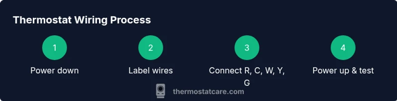
Wire in a thermostat safely by following a step-by-step approach: shut off power, identify wires, map terminals (R, C, W, Y, G), and connect as per your system. This guide from Thermostat Care helps DIY homeowners handle common 24V HVAC wiring with safety in mind. Ensure you verify the wiring with the thermostat’s manual and your HVAC equipment's wiring diagram.
Why wiring in a thermostat matters
Wiring a thermostat correctly is essential for accurate temperature control, system efficiency, and safety. When done properly, your heating and cooling equipment respond predictably, energy use stays within expected ranges, and critical safety features remain intact. According to Thermostat Care Team, a well-wired thermostat serves as the dependable bridge between your home’s HVAC equipment and the user interface on the wall. In many homes, the thermostat is the single most important control for comfort and energy bills. Before you touch any wires, make sure you understand the basic goals: establish a reliable 24-volt control circuit, provide a continuous 24-volt power supply (C wire) where required, and preserve compatibility with your specific heat or cool system. This section outlines the why behind the steps you’ll take, so you approach wiring with confidence rather than guesswork. The material here applies to common wired systems using standard terminals (R, C, W, Y, G) and to more advanced setups where a thermostat communicates with a heat pump or multiple stages. The aim is safety first, followed by accuracy and reliability.
Safety first: power, tools, and prep
Electrical work around a home HVAC system carries risk if you rush. Start by turning off power at the main breaker and, if possible, at the furnace or air handler disconnect. Use a non-contact voltage tester to confirm no voltage on the thermostat wires before touching terminals. Keep a clear work area, and remove jewelry to reduce shock risk. Gather the necessary tools so you won’t need to pause mid-task, and note the wiring colors on the old thermostat before disconnecting. If you’re replacing a non-standard or proprietary thermostat, consult the manufacturer’s compatibility notes. Always label wires as you remove them to avoid mix-ups when you reconnect. In environments with damp conditions or moisture, avoid working without protective footwear and ensure you’re standing on a dry, grounded surface. If you feel uncertain at any point, pause and seek guidance; proceeding without safe measures can damage equipment or cause injury.
Understanding wires and terminals: R, C, W, Y, G
Most 24-volt thermostats use five core connections: R (power), C (common), W (heat), Y (cool), and G (fan). The typical color mapping is a helpful guide, but colors vary by installer and age, so always rely on the labeling and the equipment’s wiring diagram rather than color alone. R provides the 24-volt feed; C completes the circuit; W tells the furnace to heat; Y engages the AC compressor; G runs the fan. Some systems use additional terminals for heat pumps, emergency heat, or multi-stage cooling, which require extra wires and more complex mapping. If your old thermostat has a jumper between R and RC or RH, the jumper may be used by your new model, but many modern thermostats auto-detect this. Before touching any wires, take a photo of the wire bundle and the terminal layout. When you reconnect, align each wire with its corresponding terminal label on the new thermostat and ensure the terminal screws are snug without over-tightening.
Check compatibility and consult wiring diagrams
First, verify your new thermostat’s compatibility with your HVAC system (gas, electric, heat pump, single-stage, multi-stage). Review the thermostat’s manual for required wires and supported configurations. If you have a C-wire shortage, many thermostats can operate with power adapters or power-extender kits, but these options vary by model. Always consult your system’s wiring diagram or the furnace control board for terminal labels and available spare conductors. If you see a terminal not listed on your thermostat, do not force a connection; instead, use an alternate configuration recommended by the manufacturer or call a pro.
Common wiring diagrams for typical homes
Below are two typical configurations you may encounter, depending on whether you have a traditional furnace or a heat pump:
- Traditional furnace (gas/oil/electric furnace with AC): R to R, W to W, Y to Y, G to G, C to C if available.
- Heat pump with auxiliary heat: R to R, Y to Y, G to G, O/B to O/B (for valve reversing), Aux/E to Aux/E, C to C if available.
For each configuration, confirm wire counts with the device’s terminal labels and the furnace board. If your thermostat recommends a different arrangement, follow the device’s wiring diagram. When in doubt, use the standard R/C/W/Y/G mapping and add only the wires your equipment requires.
Troubleshooting before you power up
Double-check the connections against the thermostat’s terminal labels. Ensure there are no stray wire strands touching adjacent terminals; trim any stray strands and re-seat wires firmly. If the thermostat still shows no power, verify that the circuit breaker is fully on and that there is 24 VAC at the furnace control board. If the display stays blank after power-up, confirm that the thermostat is compatible with your HVAC system and that you have not mixed up RC and RH connections. Keep a log of wire colors and terminal positions to help you trace faults later. If you find a wiring mismatch or a non-standard setup, pause and consult the manual or a professional.
When to call a professional
While many standard wiring tasks are within reach for confident DIYers, some homes have proprietary controls, unusual configurations, or safety concerns that require professional assessment. If you encounter an unfamiliar wire color, a missing C-wire, damaged insulation, or repeated fuse trips after wiring, stop and call a licensed HVAC technician. A pro can verify compatibility, perform a safe power-down and rewire, and ensure your thermostat communicates correctly with the furnace or heat pump. The objective is reliable comfort without risking electrical hazards or equipment damage.
Tools & Materials
- Screwdriver set (Phillips and flathead)(Flathead #2 and Phillips #2 commonly used for thermostat screws)
- Non-contact voltage tester(Test for voltage before touching wires)
- Wire stripper/culler(Prep wires to a clean, uniform length)
- Labeling tape or wire labels(Label each wire with its terminal counterpart)
- Multimeter (optional)(Verify 24 VAC if C-wire is uncertain)
- New thermostat(Ensure model supports your system (single/multi-stage))
Steps
Estimated time: 45-75 minutes
- 1
Power down and verify no voltage
Turn off the main breaker and, if available, the furnace disconnect. Use the non-contact tester to confirm there is zero voltage on the thermostat wires before touching any terminals. This protects you from shock and prevents accidental short circuits in the control board.
Tip: Double-check with the tester at both the thermostat end and the furnace end for peace of mind. - 2
Remove old thermostat and label wires
Carefully remove the faceplate and base. Gently pull the wires out enough to see their labels. Apply a label to each wire with its terminal (e.g., R, W, Y, G, C) to prevent miswiring later.
Tip: If wires are stuck, don’t tug—loosen the terminal screws slightly to free the conductor. - 3
Take a photo of the current wiring
Capture a clear photo of the terminal block and wire colors before disconnecting fully. This reference helps you reproduce the correct arrangement on the new thermostat, especially if there are non-standard wires.
Tip: Use close-up shots of the furnace/air handler boards as well if accessible. - 4
Identify system type and required terminals
Determine whether you have a traditional furnace or a heat pump and note any auxiliary heat or O/B reversing valve wires. Compare your findings against the thermostat’s wiring diagram to identify which terminals you’ll need (R, C, W, Y, G, and any specialty terminals).
Tip: If you’re unsure about O/B or Aux/E, consult the manuals or a pro before connecting. - 5
Prepare wire ends and apply labels
Trim any frayed insulation and straighten wires. If needed, trim wires to uniform length so they seat properly in the new thermostat. Reapply the labels from the prior step to the respective wires for quick reference.
Tip: Avoid nicking copper; leave a small insulation margin near the conductor for a clean fit. - 6
Connect wires to the new thermostat
Start with the common blue wire (C) if your model requires it, then move to R, W, Y, and G as appropriate. Tighten terminal screws securely but do not overtighten. If you’re missing a wire, leave the terminal empty rather than forcing a connection.
Tip: Never jumpto force connections; use the wires you have according to the device’s explicit guidance. - 7
Mount, restore power, and test basic operation
Attach the thermostat to the wall plate and restore power at the breaker. The thermostat should power up; if not, recheck the wiring order and connections. Run a quick test to confirm heat and cooling calls respond correctly.
Tip: If the display remains blank, verify compatibility and the presence of a functioning C-wire. - 8
Configure settings and perform functional test
Set the date/time, temperature units, and system type per the thermostat’s setup wizard. Test heating, cooling, and fan operation in order, noting any delays or unexpected behavior.
Tip: Document any observed issues to address before finalizing installation.
Questions & Answers
Do I need to shut off power at the breaker before wiring a thermostat?
Yes. Always disconnect power before handling thermostat wiring to avoid shock and equipment damage. Use a non-contact tester to verify there is no voltage.
Yes—power off first and test with a voltage tester to stay safe before you touch any wires.
What if there is no C-wire in my system?
Many thermostats can operate without a C-wire, but you may need a power extender kit or a different model that fits your setup. Check the thermostat manual for compatible power options.
If you don’t have a C-wire, you may need a kit or a different thermostat that doesn’t require it.
Can I reuse old wires if insulation is damaged?
No. Damaged insulation can cause shorts or fire hazards. Replace damaged wires or consult a pro for safe re-termination.
No—if the insulation is damaged, replace the wire or get professional help.
How can I tell if my thermostat is compatible with my system?
Consult the thermostat’s manual for supported configurations (single-stage vs multi-stage, heat pump, etc.). If in doubt, contact customer support or a professional.
Check the manual for what systems are supported, and ask a pro if you’re unsure.
What should I do if the thermostat shows a blank screen after wiring?
Power off and re-check wiring. Ensure the C-wire is connected if required, and confirm RC/RH connections aren’t mixed. If unresolved, professional help may be needed.
If the screen is blank, recheck connections and whether the C-wire is present; if not, get help.
Is it safe to wire a thermostat on a heat pump during DIY?
Wiring a heat pump can be more complex due to O/B and auxiliary heat. If you’re unsure, consult the thermostat manual or hire a pro.
It can be risky—heat pumps have extra wires. If unsure, get professional help.
Watch Video
What to Remember
- Power off before touching electrical wires.
- Label wires and confirm terminal mapping.
- Match wires to the correct terminals on the new thermostat.
- Verify system compatibility and safety features.
- Test operation thoroughly before finishing the install.