Where Do Thermostat Wires Go on Furnace? A Step-by-Step Guide
Learn exactly where thermostat wires land on a furnace control board, including terminal designations, color codes, safety steps, and a step-by-step wiring process you can trust.

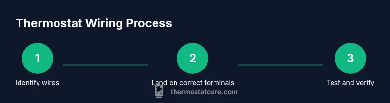
You will identify the thermostat wire bundle, locate the furnace's control board, and connect each wire to its matching terminal (R, W, Y, G, C) with the power off. This quick guide covers safety, wire labeling, common color codes, and where to land extra C-wires. Use a multimeter to verify continuity after connections for a secure setup.
Understanding thermostat wiring basics
At its core, thermostat wiring forms a low-voltage circuit that tells your furnace when to heat, cool, or fan. Most modern systems use a 24-volt control circuit with a terminal block on the furnace that accepts individual conductors from the thermostat. The wires carry signals like R (power), W (heat), Y (cool), G (fan), and C (common). If you’re asking where do thermostat wires go on furnace, you’re looking for the terminal strip on the control board and the matching entry on your thermostat cable. According to Thermostat Care, knowing the function of each wire helps you avoid misplacing wires and triggering safety issues. A correct landing point improves system reliability and reduces troubleshooting time in future maintenance.
Safety first: power off and protective gear
Before touching any furnace wiring, shut off power to the HVAC system at the main service panel and at the thermostat, if possible. Use a non-contact voltage tester to confirm there is no voltage present on the wiring. Wear eye protection and keep your workspace dry. These precautions prevent electric shocks and arc flashes, especially if your furnace is older or buried behind panels. Thermostat wiring work can expose you to 24V control circuits, which are low voltage but still hazardous if mishandled. The Thermostat Care team emphasizes conservative safety—and never work on live circuits.
Identifying thermostat wires at the furnace end
Most thermostat cables contain multiple conductors, some of which may be repurposed or unused. At the furnace end, you’ll typically see a cluster of bare copper wires with color insulation, or a bundle that disappears into the control board. The challenge is to map each color to its terminal on the board. If you’re replacing an existing thermostat, gently label each wire with its current terminal designation before disconnecting anything. This labeling will pay off when you reconnect to the correct terminals later. Remember that some older systems may use color codes that differ from the standard; always verify with the furnace manual or a label on the control board.
How to locate the furnace control board and terminal strip
Open the service panel on the furnace cabinet to reveal the control board. On the board, there will be a row of screw terminals, each labeled with a letter (R, W, Y, G, C, etc.). Some boards label the terminals directly on the plastic, others require a schematic sticker nearby. If you don’t see a clearly labeled strip, photograph the board and consult the model-specific wiring diagram from the manufacturer. Ensure you are looking at the 24V control side, not the high-voltage power connections. Understanding the terminal layout is essential for a safe and accurate landing of thermostat wires.
How to connect wires to the correct terminals
With power off, loosen each terminal screw just enough to insert the corresponding wire. Connect R to R, W to W, Y to Y, G to G, and C to C. If you lack a C-wire, you may use a jumper or consider running a new conductor, but only if your furnace supports it. After landing each wire, tighten the terminal screws firmly and gently tug each wire to confirm a secure fit. If a wire is too short, do not force it—splice or route the run more carefully, or consult a professional. Thermostat wires must be firmly secured to prevent arcing and poor contact.
Common wire color codes and their functions
Standard color coding is helpful but not universal. Red typically carries 24V power (R), White signals heat (W), Yellow signals cooling (Y), Green controls the fan (G), and Blue or Black is often used as the common (C). Some setups use alternate colors or additional wires for heat pumps, emergency heat, or separate dehumidification circuits. Always confirm each wire’s function with the furnace diagram and your thermostat’s wiring diagram before making changes. When in doubt, map the wire to the terminal by testing a gentle continuity check with a multimeter.
Troubleshooting tips if wires won't stay connected
If a wire loosens, re-strip the insulation a small amount and reinsert. Ensure the wire’s stripped length matches the terminal’s clamp depth and that there are no stray strands that could short to adjacent terminals. Use a wire nut or a small splice only if needed, and keep connections neat to avoid contact with metal parts. If the thermostat won’t read temperatures after wiring, double-check the R and C connections for power and test the voltage at the furnace terminals with a multimeter. Inconsistent operation often stems from a loose screw or an incorrect terminal landing.
Common mistakes to avoid
Avoid mixing up wires or forcing conductors into terminals not labeled for them. Do not bend conductors so tightly that insulation cracks. Do not replace a 24V transformer with a higher voltage or bypass safety features. Avoid using chewed or damaged wires—replace the cable rather than splicing. Always re-check all connections after reassembly, and power up gradually to verify operation.
When to call a professional
If you encounter a damaged control board, suspect a gas furnace gas valve issue, or you see burning smells, call a licensed hvac technician immediately. Complex wiring mistakes can lead to carbon monoxide risks or furnace shutdowns. For most basic thermostat wiring tasks, following the steps outlined above will resolve common issues, but do not hesitate to seek help for uncertainty or if your equipment is older or under warranty.
Tools & Materials
- Phillips and flathead screwdriver set(Bracket panel screws and terminal screws)
- Voltage tester or multimeter(For confirming 24V on R and C)
- Non-contact voltage tester(Quick verification before touching wires)
- Wire stripper/cetite tool(Cleanly strip insulation without damaging copper)
- Electrical tape or wire nuts(Secure splices and label wires)
- labels or masking tape(Mark each wire with its terminal)
- Flashlight or headlamp(Light dark furnace cabinet interiors)
- Replacement thermostat cable (if needed)(Extra conductors available)
Steps
Estimated time: 30-45 minutes
- 1
Power down and verify
Turn off power to both the furnace and the thermostat at the breaker. Confirm no voltage with a non-contact tester before touching any wires. This prevents shocks and accidental short circuits.
Tip: Always double-check at the breaker; the thermostat can still energize a control circuit if the furnace is powered. - 2
Access the furnace wiring
Remove the furnace access panel to expose the control board. Do not touch metal parts; keep tools away from moving components. Photograph the current layout if you're replacing an existing thermostat.
Tip: Label the panel screws to avoid misplacing them during reassembly. - 3
Label the wires
Label each thermostat wire with its current terminal or intended terminal. This helps when landing wires on the new board and prevents miswiring.
Tip: Use pre-cut labels or masking tape and a felt-tip marker for clear, durable marks. - 4
Disconnect and prep wires
Loosen terminal screws and remove each wire with care. If a wire is frayed, trim and re-strip to proper length. Avoid nicking copper during stripping.
Tip: Keep stripped ends uniform length to ensure good contact in the terminal clamp. - 5
Land wires on matching terminals
Reattach each wire to its corresponding terminal: R to R, W to W, Y to Y, G to G, C to C. Ensure no stray strands touch adjacent terminals.
Tip: If a C-wire is absent, check for a spare conductor or consider adding one in a safe, code-compliant way. - 6
Secure and inspect
Tighten all screws firmly and tug lightly on each wire to confirm a solid fit. Reassemble the furnace panel and return power. Observe the thermostat for correct operation.
Tip: Keep the area clean and free of tools before restoring the panel. - 7
Test system operation
Set the thermostat to heat, then verify the furnace responds and cycles properly. If nothing happens, re-check R and C for voltage and verify that other wires are on their correct terminals.
Tip: If the system doesn’t respond, consult the thermostat manual for terminal mapping and consider a professional check.
Questions & Answers
Do I need a C-wire for my thermostat?
Not all thermostats require a C-wire. Battery-powered thermostats can run without it, but many modern units need C-wire for reliable power. Check your thermostat manual and furnace compatibility before deciding.
A C-wire isn’t always required, but many modern thermostats do rely on it for consistent power. Check your device’s manual and your furnace wiring diagram.
What if the color codes don’t match standard colors?
Color codes aren’t universal. Always verify terminals with labels and the furnace diagram. If in doubt, map wires using resistance testing or consult the wiring diagram.
Color codes aren’t universal. Use the terminal labels and your furnace diagram to map wires correctly, and seek help if unsure.
Can I connect thermostat wires from the thermostat side only?
No. You must verify the furnace terminal connections as well. Incorrectly landing wires on the thermostat side can leave the system unresponsive or damaged.
No, you should verify the furnace terminals too. Incorrect wiring on either end can cause the system to fail.
What should I do if the thermostat won’t power on after wiring?
Check that R is delivering 24V and that C is present if your thermostat requires it. Recheck terminal alignment and ensure screws are tight. If power still doesn’t reach the thermostat, consult a professional.
If the thermostat isn’t powering on, verify 24V between R and C, and ensure all connections are tight. If needed, call a pro.
Is it safe to test for 24V with a multimeter?
Yes, provided you know how to safely place the probes on R and C without touching live metal. Use proper PPE and follow manufacturer instructions.
Yes—carefully test for 24V between R and C with a multimeter, following all safety guidelines.
What if a wire won’t fit into the terminal?
Trim the insulation back a bit more and ensure the wire strand isn’t frayed. If the terminal still won’t accept it, consider replacing the wire run with a properly sized conductor.
If a wire won’t fit, trim a little more and reinsert. If it still won’t go, you may need a different conductor.
Watch Video
What to Remember
- Identify each terminal and wire before reconnecting.
- Always power down and test before touching wires.
- Label wires to prevent miswiring and misplacement.
- Confirm system operation with a controlled test after wiring.
- If unsure, consult a professional—safety comes first.