Heat Pump vs Conventional Thermostat Wiring: A Practical Guide
Compare heat pump wiring with conventional thermostat wiring to understand wiring needs, compatibility, and safety. Practical guidance for installation, troubleshooting, and selecting the right setup for your home.

Heat pump wiring and conventional thermostat wiring differ in power needs, wire types, and control strategies. This quick comparison helps homeowners decide which setup suits a heat pump system and a standard furnace. For many homes, the key decision is whether a dedicated C-wire and reversing valve control are required. See our full chart for details and step by step guidance.
Overview: heat pump wiring vs conventional thermostat wiring
Deciding between heat pump wiring and conventional thermostat wiring involves understanding how each system is controlled and powered. In the heat pump vs conventional thermostat wiring scenario, the heat pump often requires additional signals beyond standard heat and cool calls. According to Thermostat Care, proper wiring hinges on a dedicated common (C-wire) and, for many heat pumps, a reversing valve control that tells the outdoor unit which mode to operate in. The exact wiring layout can vary by brand and model, but the principle remains: heat pumps rely on more complex signal wiring to coordinate indoor comfort with outdoor equipment. This block sets the stage by describing the core goals: reliable control, safety, and compatibility with your thermostat features. For DIYers, the first step is to map existing wires, identify the C-wire, and confirm that the thermostat supports heat pump operation.
Core Electrical Differences
At the heart of the comparison between heat pump wiring and conventional thermostat wiring is the electrical signaling used to control equipment. Conventional setups typically use a straightforward 24 volt circuit with R powering the thermostat and Y, G, and W making basic calls for cooling, fan, and heating. A heat pump adds complexity by including a reversing valve signal, commonly labeled O or B, and often an auxiliary heat signal W/Aux for backup heating. Some systems also bring a dedicated heat pump cool call for staging and defrost control. Because of these additions, heat pump wiring usually requires an extra conductor or two beyond the standard four wires. Homeowners should expect longer installation time and a careful check of wire color coding to avoid miswiring. The takeaway is that wiring goals shift from simple on off control to robust coordination of indoor and outdoor equipment.
The C-Wire and Power Requirements
Many thermostat models rely on a constant power source from the HVAC control circuit. The C-wire provides a return path for that power, keeping the thermostat powered during periods of heavy use. For heat pumps, a C-wire is frequently essential to power the thermostat’s more advanced features and to support the reversing valve actuator. If the existing cable lacks a C-wire, options include running a new conductor, upgrading the thermostat to a battery powered model with limited features, or using a power extender kit if the installer approves. However a power extender can complicate diagnosis. Always ensure the C-wire is continuous from the HVAC control board to the thermostat and that the wire gauge matches the manufacturer's recommendations.
Reversing Valve and System Control
A critical control line in heat pump wiring is the reversing valve signal. When the thermostat calls for cooling, the reversing valve shifts refrigerant flow so the outdoor unit handles cooling; on heat call the valve may switch direction for heating. The O or B wire carries this signal and must be wired to the correct terminal on both the thermostat and the outdoor unit. Incorrect wiring can cause the system to heat when cooling or refuse to run at all. For many older thermostats the reversing valve is not supported or is misinterpreted by the control software, resulting in erratic cycling or inefficient operation. Modern thermostats designed for heat pumps ship with clear labeling for O and B and can auto detect the valve type. Always verify that your outdoor unit and thermostat share the same valve wiring convention.
Thermostat Compatibility and Feature Sets
Not all thermostats are created equal when it comes to heat pump wiring. Some basic models support heat and cool only and may not manage the reversing valve or auxiliary heat correctly. Other thermostats are explicitly designed for heat pump systems and offer advanced features such as stage control, adaptive defrost, and energy saving modes. When selecting a device, check the manufacturers wiring diagram to confirm the presence of R, C, Y, G, W, and O/B terminals. Confirm whether the thermostat expects a C-wire and if the O/B signal is compatible with your heat pump brand. For homes with multiple zones or a heat pump with auxiliary heat, consider a thermostat that supports multi stage heat pump control. Reading reviews and cross checking with your HVAC installer increases the odds of a smooth setup.
Wiring Diagrams: Common Configurations
Common configurations fall into several patterns depending on equipment. A typical heat pump system uses R, C, Y, G, O/B, W/Aux. Some configurations add a second stage W2 or E for auxiliary heat. In a conventional non heat pump setup you may see R, C, Y, G, W only. A simple diagram helps: thermostat R connects to R on the control board; Y to Y; G to G; W to W; O/B to reversing valve; C to C. Outdoor unit connections share the same signals through the furnace or air handler. If your home has a separate air handler, you may need a common wire from the air handler to the thermostat. Always label wires before disconnecting anything.
Safety, Codes, and Permits
Electrical work can be dangerous. Always turn off power at the breaker before touching thermostat wiring. Follow local electrical codes for low voltage wiring, and keep questions in the box accessible. In many jurisdictions, thermostat wiring upgrades for heat pumps require a permit or a qualified technician. Use a multimeter to verify voltage and continuity and never rely on guesswork. If you see damaged insulation, exposed conductors, or a burnt smell, stop and call a pro. When upgrading components, ensure that all devices are rated for low voltage 24V operation and that the thermostat is UL listed for your system.
Energy Efficiency Implications
Proper heat pump wiring can improve efficiency by enabling accurate temperature control and quicker recovery. A correctly wired reversing valve and auxiliary heat control helps avoid short cycling and reduces runtime, which can lower energy use over a season. However improper wiring can increase energy consumption and wear on the outdoor unit. Smart thermostats that support heat pump optimization can adjust defrost cycles and compressor lockouts, but they rely on correct wiring to function. In practice, homeowners should combine good wiring with appropriate thermostat settings to maximize efficiency. Thermostat Care's analysis shows that wiring quality is a major determinant of performance for heat pump systems in typical homes.
Troubleshooting Common Wiring Issues
Field tests and symptoms help narrow down wiring problems. If the thermostat shows no power, check the C-wire continuity and the R connection. If the reversing valve seems stuck, test O/B wire with a diagnostic mode on the thermostat, and verify the outdoor unit wiring at the control board. A common sign of miswiring is the wrong equipment running in the wrong season. If the heat pump runs but the auxiliary heat engages unexpectedly, inspect the W/Aux wire and ensure it is connected to the correct terminal. Loose terminals or corroded connections can cause intermittent behavior; reseating and cleaning terminals can help. Always return to the basic check list before replacing components: confirm wire labeling, verify polarity, and re-test with the system powered and cycle through heat and cool to confirm operation.
DIY Wiring Steps and Checklists
Before you touch anything, turn off power, label each wire, and take a photo of the current configuration. Start by verifying the presence of a C-wire and ensure the thermostat has a compatible O/B setting. Mount the thermostat, connect R, C, Y, G, and W as labeled, and attach the O/B wire to the correct terminal. If you lack a C-wire, consider running a new conductor or using a power extender kit per the thermostat manufacturer guidance. Test the system with a basic heat and cool cycle, then enable advanced features like adaptive defrost or energy saving modes if supported. Document any changes and keep the original wiring diagram for reference. If you feel unsure at any point, stop and consult a pro to avoid damaging the equipment or creating a safety hazard.
When to Hire a Pro
DIY wiring can be rewarding, but heat pump wiring carries higher risk and complexity. If your system involves multiple stages, a variable speed compressor, or a dedicated outdoor coil, a licensed HVAC technician can insulate the risks, ensure code compliance, and verify compatibility with the thermostat. Pro installation also helps with warranty coverage, because many manufacturers require professional service for voiding. A pro can perform a thorough thermostat compatibility check, confirm C-wire integrity, and coordinate any changes to defrost cycling and reversing valve operation. When in doubt, schedule a consultation with a technician who specializes in heat pump systems to prevent costly mistakes.
Common Mistakes to Avoid
Rushing through a wiring upgrade without documenting existing wires, mislabeling terminals, or assuming a C-wire is unnecessary. Reversing valve signals, O/B miswiring, or using a thermostat that lacks heat pump support can lead to improper cycling and poor comfort. Avoid pairing a thermostat that does not support your system and avoid introducing extra wires without confirming compatibility. Finally, never power up a thermostat or outdoor unit while handles and wire bundles are still loose; power should be off during any testing or changes.
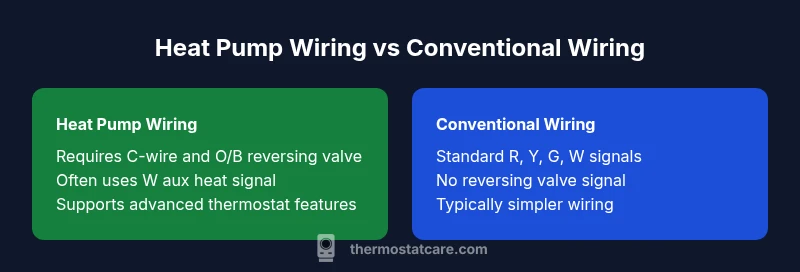
Comparison
| Feature | Heat pump wiring | Conventional thermostat wiring |
|---|---|---|
| Wiring requirements | Requires C-wire and O/B reversing valve control | Standard R, Y, G, W without reverse valve control |
| Power source | 24V control with dedicated C-wire common | 24V control with basic R and returns |
| Thermostat compatibility | Supports heat pump features on modern thermostats | Works with basic thermostats that cover heat and cool |
| Installation complexity | Moderate to high depending on existing wiring | Low to moderate |
| Cost context | Moderate to high due to C-wire and valve wiring | Low to moderate |
| Best for | Homes with heat pump systems and objective valve control | Homes with conventional forced air without heat pump features |
Upsides
- Improved system efficiency when wired correctly
- Better compatibility with smart thermostats and advanced features
- Clearer diagnostic signals for wiring issues
- Future proofing for upgrades and zoning
The Bad
- Higher upfront wiring complexity and potential rework
- Additional materials cost such as extra wires or adapters
- Professional installation may be required to ensure safety
Heat pump wiring generally offers better control and efficiency when correctly implemented
Choose heat pump wiring for systems requiring reversing valve control and advanced thermostat features. For simple setups, conventional wiring may suffice, but verify compatibility with your chosen thermostat and system.
Questions & Answers
Do heat pumps always require a C-wire?
Most heat pumps benefit from a C-wire to power the thermostat and enable advanced features like reversing valve control. Some battery powered thermostats can operate with limited functionality when a C-wire is absent.
Most heat pumps need a C-wire for full features, but some battery powered thermostats work with limited functionality.
Can I install heat pump wiring myself?
You can replace a thermostat with basic knowledge of low voltage wiring, but wiring a heat pump involves complex signals like O B and W Aux. If you are unsure, consult a pro to avoid damage or safety risks.
DIY is possible with care, but heat pump wiring is tricky. When in doubt, hire a pro.
What is the reversing valve and why is it important?
The reversing valve decides whether the system is in heating or cooling mode. The O or B wire must connect correctly to ensure proper operation; miswiring can cause wrong cycling and inefficiency.
The reversing valve tells the system which way to run, so wiring it correctly is essential.
Are there code requirements for wiring heat pumps?
Local codes may require licensed installation, permits, and inspection for heat pump wiring upgrades. Always follow manufacturer guidelines and check with local authorities.
Local codes may require a pro and a permit for wiring upgrades.
What about multi stage heat pumps and wiring?
Multi stage heat pumps add wires for additional stages. Ensure your thermostat supports multiple stages and that Y1/Y2, O/B, and AUX are wired correctly.
If you have a multi stage heat pump, choose a compatible thermostat and wire it correctly.
What to Remember
- Assess C-wire needs before upgrading
- Confirm thermostat compatibility with heat pump features
- Expect higher upfront complexity for heat pump wiring
- Use a professional for multi stage or complex setups
- Prioritize safety and code compliance during installation