Heat Pump Thermostat Wiring Diagram: A Practical Guide
Learn how to read and apply a heat pump thermostat wiring diagram. Step-by-step wiring, common wire colors, safety checks, and troubleshooting for homeowners.

Goal: read and follow a heat pump thermostat wiring diagram to wire or troubleshoot with confidence. You’ll identify the thermostat terminals, map them to system wires, and verify power safely. Before starting, gather a multimeter, screwdrivers, wire stripper, and the system’s diagram. According to Thermostat Care, always shut off power at the breaker and outdoors before touching any wiring.
Understanding the Heat Pump Wiring Diagram
A heat pump thermostat wiring diagram is a map of how the thermostat connects to the indoor air handler and outdoor unit. It shows the terminal labels on the thermostat base (R, C, Y, G, O/B, Aux/E, W1) and the corresponding control wires from the heat pump system. Knowing how to read this diagram helps you wire or troubleshoot without guessing, reducing the risk of damage to equipment or voiding warranties. According to Thermostat Care, the wiring diagram is the single best tool for ensuring your heat pump operates reliably in heating and cooling modes, especially in climates where reversing valve operation matters most. Start by locating the system’s control board and the thermostat connection block, then compare the wire colors and functions to the diagram. If you find discrepancies between colors and terminal labels, rely on the diagram rather than wire color alone. When in doubt, pause and re-check before connecting to a live circuit.
Common wire colors and functions in heat pump systems
Heat pump wiring uses color codes to indicate function, but colors can vary by installer. The diagram will confirm the exact mapping for your system. Typical terminals include:
- R ( Rc / Rh ): 24V power from the transformer (red wire).
- C: Common return path for the 24V circuit (blue or brown).
- Y: Compressor contactor (cooling). Often yellow.
- G: Indoor fan relay (green).
- O/B: Reversing valve control (orange or brown). Determines heat/cool mode switching.
- Aux/E: Auxiliary/backup heat (white).
- W1: Emergency heat (auxiliary heat in some systems).
- L: System monitor (optional on some units).
Always verify functions with the diagram since some installations reuse colors for different signals. In a heat pump, correctly identifying O/B, Y, and C is crucial for reliable operation and for avoiding nuisance short-cycles or improper defrost behavior.
Reading the diagram: terminals and controls
A typical heat pump diagram shows a row of terminals on the thermostat and a matching set of wires from the system. The diagram’s labels tell you which wire goes to which terminal. Look for:
- Terminal designations (R, C, Y, G, O/B, Aux/E, W1) and any special notes for heat pump configurations.
- Wire counts on each terminal to ensure you’re transferring all necessary signals.
- Any jumpers or configuration options specific to your model (some thermostats require jumpers for conventional vs. heat pump modes).
By cross-referencing the diagram with what you see at the wall, you can confirm a safe, accurate mapping before activating power. If a color doesn’t seem to align with the diagram, rely on the label rather than color alone.
Troubleshooting common wiring pitfalls
Wiring mistakes are the top cause of thermostat-related issues on heat pumps. Common problems include mislabeling R and C, connecting Y to a non-contactor circuit, or leaving O/B unconnected when a reversing valve is required. If your system doesn’t respond after wiring, double-check each terminal against the diagram, confirm the jumper settings, and verify there are no loose connections. A common-sense approach is to re-verify power state, re-seating wires, and rechecking wire gauge compatibility with terminal clamps.
If you encounter an unresponsive system, test for voltage at the R and C terminals with a multimeter, and ensure the thermostat is receiving power before testing control signals. Remember: safety first, power off always during any wiring check.
Wiring for heat pumps with auxiliary heat and reversing valves
Heat pumps rely on a reversing valve (O/B) to switch between heating and cooling. If your unit uses auxiliary heat (Aux/E or W1), you’ll need to connect those wires correctly so the system engages auxiliary heat during cold conditions. Some thermostats require configuring the outdoor sensor or climate settings to honor the reversing valve behavior. Always map O/B, Y, and Aux/E carefully and test in both heat and cool modes. If you’re unsure about O/B orientation, consult the system manual or contact a pro—incorrect wiring can cause improper valve operation and reduced efficiency.
Safety considerations and code compliance
Low-voltage thermostat wiring is generally safe if you follow basic precautions, but mistakes can damage equipment or cause shocks. Always shut off power at the breaker and outdoor disconnect before touching any wires. Wear insulated tools and use a voltage tester to confirm zero potential on conductors. Ensure your wiring work meets local electrical codes—some regions require a licensed HVAC technician for certain installations or changes in the outdoor unit wiring. Keep the thermostat’s mounting clean and dry, and avoid creating stressed wire runs that could loosen connections over time.
How to choose a thermostat compatible with heat pumps
When selecting a thermostat for a heat pump, verify compatibility with heat-pump systems, including support for O/B reversing valve, Y (cooling), Aux/E, and C (common) terminals. Look for features like adaptive defrost control, energy-saving modes, remote sensor support, and compatibility with your HVAC brand. If your system uses multiple stages of heat or emergency heat, ensure the thermostat can handle those signals. In practice, a well-supported heat pump thermostat will simplify wiring diagrams and reduce troubleshooting time, a point emphasized by Thermostat Care in their guidance to homeowners.
Quick-start checklist before you wire
- Confirm power is off at the breaker and outdoor disconnect.
- Photograph the existing wiring and label each wire.
- Compare the wires to your heat pump’s wiring diagram and the thermostat base.
- Prepare a clean, organized workspace with labeled connectors.
- Have replacement thermostat screws, a spare wire, and a thermometer handy to verify temperature responses after wiring.
Next steps and deeper resources
If you’ve reached this point and the wiring diagram matches your system, proceed to the Step-by-Step Wiring Guide to finalize connections and test operation. For ongoing projects, keep a copy of the wiring diagram in your toolbox and note any deviations you encounter. When in doubt, consult your HVAC manual or a licensed technician to ensure safety and optimal performance.
Tools & Materials
- Non-contact voltage tester(Verify zero voltage at the thermostat wires before touching.)
- Multimeter(Measure voltage and check resistance if needed.)
- Screwdrivers (Phillips and flat-head)(Insulated handles recommended; use appropriate size.)
- Wire strippers/cutters(Prepare wires for terminal insertion without damage.)
- Electrical tape or wire nuts(Secure and insulate connections after wiring.)
- Wire labels or masking tape(Label wires to map to thermostat terminals.)
- Replacement thermostat with heat-pump compatibility(Ensure it supports R, C, Y, G, O/B, Aux/E, W1.)
- Safety glasses(Eye protection during wiring work.)
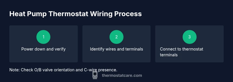
Steps
Estimated time: 30-60 minutes
- 1
Power down the system
Switch off power at the main breaker and outdoor disconnect. Use the non-contact tester to confirm zero voltage on thermostat wires before touching anything. This protects you and the equipment from shocks or arcs.
Tip: Always assume wires can carry voltage even if the display shows zero; retest after removing covers. - 2
Document existing wiring
Remove the thermostat cover and photograph the current wiring. Label each conductor with tape to record its terminal mapping. This reference helps you map to the new thermostat without guessing.
Tip: If you’re unsure about a wire’s function, avoid removing it until you’ve labeled and verified with the diagram. - 3
Identify system type and wire roles
Consult the heat pump diagram: verify R, C, Y, G, O/B, Aux/E, and W1 wires, and note any L or other control signals. Confirm the presence of a reversing valve and auxiliary heat, as these affect wiring choices.
Tip: If your system has multiple stage heat or unusual labels, check the manufacturer’s guide. - 4
Prepare wires for new terminals
Trim and strip wires as needed, ensuring clean copper exposure. Keep conductors untwisted and straight to avoid frayed strands at terminals.
Tip: Use even strip lengths and avoid nicking copper—nicks can cause poor connections. - 5
Connect wires to the new thermostat
Attach wires to the corresponding terminals (R to R, C to C, Y to Y, G to G, O/B to O/B, Aux/E to Aux/E, W1 to W1). Double-check that the O/B valve and Aux heat signals align with the diagram and climate settings.
Tip: If your thermostat requires a jumper for heat pump mode, install it per the manual exactly as shown. - 6
Restore power and perform a basic test
Reapply power and run a quick test of cooling, heating, fan, and defrost functions. Observe for abnormal sounds, lagging responses, or incorrect reversing valve behavior.
Tip: Use the thermostat’s auto-test feature if available to validate mode transitions. - 7
Fine-tune and document changes
If any settings deviate (e.g., O/B orientation or waking/hold settings), adjust per the diagram and climate. Save a note of changes and keep the original diagram as a reference.
Tip: Keep a dated change log inside the thermostat compartment or in your project notes.
Questions & Answers
What is a heat pump thermostat wiring diagram?
A heat pump thermostat wiring diagram is a schematic that shows how thermostat wires connect to a heat pump system, mapping terminal labels (R, C, Y, G, O/B, Aux/E, W1) to actual conductors. It helps ensure correct wiring and safe operation.
A wiring diagram shows which wire goes to which terminal, guiding safe, correct connections.
How do I identify the C-wire in heat pump systems?
The C-wire is the common wire returning to the 24V transformer. It’s often blue or brown and labeled C on the diagram. If it’s missing, you may need an adapter or a pro to install a proper common.
Look for the common wire labeled C; if missing, you may need a pro to help.
Can I wire a thermostat to a heat pump myself?
DIY wiring is possible for basic setups if you follow the wiring diagram precisely and observe safety steps. More complex configurations (multi-stage heat, unusual reversing valve) are better handled by a licensed technician.
You can, with caution, but complex setups are best left to a pro.
What safety steps are essential before wiring a heat pump thermostat?
Power down at the breaker and outdoor disconnect; verify zero voltage with a tester; use insulated tools and avoid live connections. If in doubt, pause and seek professional help.
Power off, verify zero voltage, work with insulated tools.
How do I know if my thermostat is compatible with my heat pump?
Check the thermostat’s specifications for heat-pump support, O/B control, and C-wire compatibility. Ensure it supports your system’s stage count and auxiliary heat if applicable.
Check the features list for heat-pump compatibility and O/B support.
Watch Video
What to Remember
- Identify and map every wire to its terminal before connecting.
- Power off first, then verify with a tester to ensure safety.
- Verify O/B and Aux/E wiring for proper heat pump operation.
- Test all modes (heat, cool, fan) after wiring and document changes.
- Use the wiring diagram as the primary guide, not color alone.