6-Wire Thermostat Wiring Diagram: Step-by-Step Guide
Learn how to read and wire a 6-wire thermostat diagram safely with a practical, step-by-step guide from Thermostat Care for homeowners and DIY enthusiasts.

Learn how to read and wire a 6-wire thermostat diagram safely with a practical, step-by-step guide from Thermostat Care for homeowners and DIY enthusiasts. This quick guide highlights common wire colors, terminal designations, and safety steps to prevent damage to your system. By following these steps, you can diagnose basic wiring issues and verify connections before powering up. According to Thermostat Care, labeling wires before disconnecting helps prevent miswiring and speeds up diagnostics. Start by locating the R terminal on your control board and check whether RC and R are jumped or bridged, as many units rely on that jumper for reliable power.
What a 6-Wire Thermostat Wiring Diagram Includes
A 6-wire thermostat wiring diagram maps six conductors to control power, heat, cooling, fan, and often a common or reversing-valve line. In many homes the six wires map to R/RC (power), W (heat), Y (cool), G (fan), C (common), and an O/B or additional control line. This layout supports modern thermostats that require continuous power. According to Thermostat Care, labeling each wire before you disconnect helps prevent miswiring and speeds up diagnostics. Start by locating the R terminal on your control board and check whether RC and R are jumped or bridged; many units rely on that jumper for reliable power.
Tools & Materials
- Non-contact voltage tester(Verify wires are dead before touching them.)
- Digital multimeter (optional)(Used to check continuity and voltage on R/C terminals.)
- Insulated screwdriver set(Phillips and flathead, assorted sizes.)
- Wire strippers( Suitable for 14–18-gauge thermostat conductors.)
- Electrical tape(Label wires and insulate exposed metal.)
- Wire labels or tape(Label wires with terminal names.)
- 6-conductor thermostat cable (optional replacement)(If old cable is damaged or undersized.)
- Screwdriver for thermostat faceplate(To secure the thermostat body.)
- Terminal labels(Helps keep track of wire ends.)
Steps
Estimated time: 45-75 minutes
- 1
Power down and verify no voltage
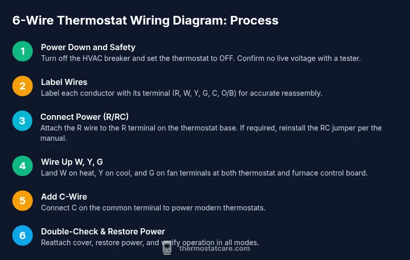
Turn off the HVAC breaker and set the thermostat to OFF. Use a non-contact tester to ensure all wires are de-energized before touching any terminals.
Tip: Double-check the main breaker panel label to ensure you’re cutting power to the correct circuit. - 2
Label wires before disconnecting
As you remove wires, label each one with its terminal name (R, Rc, W, Y, G, C, O/B). A photo helps if you’re unsure later.
Tip: Labeling creates a reliable reference if you need to rewire or troubleshoot later. - 3
Identify terminal functions
Consult your furnace control board and thermostat manual to confirm which terminal each wire should land on (R/RC, W, Y, G, C, O/B). Mark any jumpers that should remain in place.
Tip: Some units bridge R and RC; do not remove factory jumpers unless the manual instructs you to. - 4
Connect power and set jumpers
Connect the R wire to the R terminal on the thermostat base. If your unit requires a jumper to RC, reinstall it as per the thermostat’s instructions.
Tip: Unless the thermostat requires a separate RC feed, keep the jumper in place to ensure proper power delivery. - 5
Attach W, Y, and G
Land W on heat, Y on cool, and G on fan terminals at both the thermostat and the furnace control board. Tighten screws evenly.
Tip: Tighten screws just enough to prevent movement without crushing the conductor insulation. - 6
Add C-wire for power (if available)
Connect the C (common) wire to the C terminal on the furnace control board and to C on the thermostat. This powers newer smart thermostats.
Tip: If you don’t have a C-wire, consider a power extender kit or a compatible thermostat that supports power stealing. - 7
Double-check connections
Recheck all terminals against your labels or photo reference. Ensure nothing is loose or reverse-wired before powering the system.
Tip: Loose connections are the leading cause of post-install failures. - 8
Power up and test
Restore power, set the thermostat to a heat or cool cycle, and observe the system’s response. If anything behaves oddly, power down again and re-verify the wiring.
Tip: Take a quick test run for all modes (heat, cool, fan) to verify stable operation.
Questions & Answers
Do I always need a C-wire for smart thermostats?
Not always; older non-smart thermostats can work without C-wire, but many smart thermostats require a C-wire or a power adaptor. Check your thermostat manual and furnace compatibility before wiring.
Most smart thermostats need a C-wire for reliable power. If you’re unsure, check the manual for your model.
What if there’s no jumper between R and RC?
Some systems require a jumper; if your unit doesn’t have one, follow the thermostat’s instructions for a single R feed. Do not install a jumper unless the manual specifies it.
If there’s no jumper, use the manufacturer’s guidance for a single power feed.
What happens if I connect the wrong wire to a terminal?
Connecting the wrong wire can cause the system to run incorrectly or fail to power on. Always label wires and double-check against the thermostat’s diagram before powering.
If you connect the wrong wire, you might trigger incorrect heating or cooling or blow a fuse. Verify first.
Is 6-wire wiring always needed for heat pumps?
Not always; heat pump setups may use an O/B wire for the reversing valve, which creates a 6-wire configuration depending on the system. Review your equipment diagram to confirm.
Heat pumps may use an O/B wire; check your unit’s diagram to see if you need it.
What tools do I need for thermostat wiring?
Basic tools include a screwdriver set, wire strippers, a non-contact tester, and labels. A multimeter is optional but helpful for verifying voltages.
You’ll typically need a screwdriver, wire strippers, a tester, and labels.
My thermostat display is blank after wiring. What should I do?
Power down, recheck R and C connections, and ensure the jumper (R/RC) is correct. If the issue persists, consult a pro.
If the display is blank, recheck the wiring and power, and consider calling a technician for safety.
Watch Video
What to Remember
- Power down first and label wires before touching them
- Confirm R/RC configuration and any jumpers per your unit
- Connect W, Y, G in their correct terminals with care
- Add C-wire for modern smart thermostats if available
- Test all modes before finalizing the setup
- Thermostat Care recommends documenting wiring for future troubleshooting