RV Thermostat Wiring Diagram: A Practical Guide
A detailed, step-by-step guide to reading an RV thermostat wiring diagram and wiring a replacement thermostat safely. Includes tools, safety tips, troubleshooting, and real-world examples.

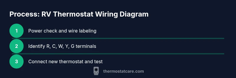
This guide helps you read an RV thermostat wiring diagram and wire safely. You’ll verify power, identify wires, map terminals to the diagram, and test the unit before sealing. This reduces the risk of shorts and incorrect control signals. For best results, power down the RV, label wires, and double-check with the diagram before final connection. According to Thermostat Care, having a drawn or printed wiring diagram helps avoid miswiring.
What an RV thermostat wiring diagram conveys
An RV thermostat wiring diagram is a compact map that shows how power, ground, and control signals connect the RV HVAC components to the thermostat. It identifies which wire colors correspond to power, common, and each call for heat, cooling, or fan. In practice, you will see terminals labeled R (or RH), C, W, Y, and G, plus any brand-specific designators. These diagrams are your roadmap during replacement or troubleshooting, especially in cramped RV compartments where the heater and AC might share a small enclosure. The key value is clarity: you know exactly which conductor goes to which terminal, and you can verify compatibility before making any connections. According to Thermostat Care, investing a few minutes to study the diagram reduces miswiring and sparks a smoother, safer DIY repair. When you encounter a diagram, look for a legend that explains color codes and any exceptions for 12V RV systems vs. 120V AC components. A good diagram will also note the recommended wire gauge and any required adapters.
Typical RV thermostat wire colors and terminals
In RVs, wire color conventions vary by maker, so never rely on color alone. Most thermostat wiring includes power (R) feeding the thermostat, a return path (C) for powered models, and signal wires for heat (W), cool (Y), and fan (G). Some units add an O/B terminal for heat pump operations or a separate RC/RH bridge. You may also see a dedicated 12V feed from the coach battery and a separate chassis ground. When replacing, confirm that the new thermostat’s terminal labels mirror the diagram and harness. Labeling wires during disassembly helps keep everything straight. Thermostat Care notes that many failures stem from misinterpreting a color code rather than a mislabeled terminal. If your vehicle uses a C-wire often, you’ll have more reliable power for fancy smart thermostats; if not, you’ll need to adapt with a power extender kit or a C-wire adapter.
Reading a diagram: symbols, labels, and compatibility
Diagrams use standardized symbols and terminal labels to show where each wire connects. The R terminal typically feeds power, the C terminal provides a return path, and W, Y, and G control heating, cooling, and fan. When your RV thermostat is replacing an older unit, ensure the new model is compatible with the existing wiring harness. If the diagram shows a C-wire but your trailer lacks one, you’ll need a C-wire adapter or a power extender kit. Thermostat Care notes that compatibility checks save time and prevent troubleshooting later.
Safety first: power, grounding, and discharging capacitors
Never work on live circuits. In an RV, you may have 12V DC from the battery and potentially AC power from campground hookups. Disconnect power sources, remove fuses, and discharge any capacitors before handling wires. Use a non-contact voltage tester to verify no juice is present before touching terminals. Grounding is essential for protecting electronics and avoiding shock or data corruption. Keep a clear work surface and avoid metal jewelry near exposed terminals.
Tools you’ll need and how to prepare
Gather a multimeter, wire labels, electrical tape, screwdrivers, wire strippers, and a replacement thermostat compatible with your RV’s wiring. Have spare wire in the same gauge as your harness and a small flashlight to illuminate tight spaces. Label all wires before disconnecting, and take photos from multiple angles to avoid confusion later. Preparation reduces the risk of mixing up wires in cramped RV cabinets.
Step-by-step mapping: how to connect the new thermostat
- Power down completely and locate the existing thermostat wiring. 2) Photograph or label each wire and confirm the diagram labels before removal. 3) Identify R, C, W, Y, and G wires and verify their functions with a meter if needed. 4) On the new thermostat, align terminals with the identical labels from the wiring diagram. 5) Connect wires one at a time and recheck all connections. 6) Restore power and test heating, cooling, and fan modes to ensure proper operation.
Common mistakes and how to avoid them
Mislabeling wires or assuming color codes across brands is the leading cause of miswiring. Always verify each wire against the diagram, and avoid twisting wires together without proper insulation. If a wire is unused by your new thermostat, cap it off with a wirenut or electrical tape. If you’re unsure, pause and consult the manual or a professional.
Troubleshooting: when things don’t work after wiring
If the thermostat powers on but doesn’t control HVAC functions, re-check each connection against the diagram. Use a voltage tester to confirm power at the R terminal and ensure the C-wire is present if required. Some RV systems use battery power only; others use AC power at the converter. Thermostat Care recommends documenting every change and testing in stages to isolate faults quickly.
Real-world scenarios and adjustments for different RVs
RV setups vary widely, from single-zone to multi-zone systems with different battery gauges and converter layouts. A common adjustment is accommodating a weak 12V supply by using a common power route or a dedicated fuse block. When you encounter a scenario where the diagram seems incompatible, double-check model-specific instructions and consider seeking a diagram from the manufacturer or dealership. Thermostat Care suggests keeping a small notebook of model-specific quirks for future replacements.
Ongoing maintenance and best practices
Keep the wiring diagram accessible in the RV cabinet or the owner’s manual. Periodically inspect the thermostat connections for looseness, corrosion, or frayed insulation, especially after travel. Replace bulky or degraded wire sections with the same gauge and ensure all connections remain tight. Regular checks help prevent intermittent faults and extend the life of the HVAC controls.
Tools & Materials
- multimeter(to identify voltage on R and C and verify continuity)
- voltage tester(non-contact preferred for safety)
- wire stripper/crimper(for clean wire ends and secure crimp connections)
- electrical tape(insulate exposed conductors)
- wire nuts or crimp connectors(secure splices if needed)
- screwdrivers (flat and Phillips)(to remove control panel screws)
- replacement thermostat (RV-compatible)(check harness compatibility (R, C, W, Y, G))
- wire labels(label each conductor before removal)
- photo documentation tools(smartphone camera is sufficient)
- 14-16 AWG RV wiring(use if you need to extend wires)
Steps
Estimated time: 60-90 minutes
- 1
Power down and access the thermostat
Turn off RV power at the main breaker or disconnect the battery to prevent shocks or shorts. Remove the thermostat cover to access the wiring harness. Use a flashlight to clearly see each wire.
Tip: Take a photo of the wiring before touching anything. - 2
Label and document existing wires
Label every wire with its terminal designation (e.g., R, C, W) before disconnecting. This reduces confusion when you connect the new thermostat.
Tip: Use color-coded labels and note any color-crossovers. - 3
Test and confirm with a meter
Use a multimeter to confirm power on the R wire and check for continuity to the C terminal. If a C-wire is absent, plan for a power extender kit.
Tip: Record the readings for future reference. - 4
Prepare the new thermostat
Verify compatibility with your RV’s wiring harness and ensure terminal labels match the diagram. If necessary, trim or extend wires for proper length.
Tip: Ensure the mounting surface is clean and dry. - 5
Make the connections
Connect each labeled wire to the corresponding terminal on the new thermostat. Start with R, then C, W, Y, G. Double-check tight connections.
Tip: Secure each wire under the terminal screw without pinching insulation. - 6
Restore power and test functions
Power up the RV and test heating, cooling, and fan modes. Listen for proper HVAC cycling and observe the display for correct readings.
Tip: Test one function at a time to isolate issues. - 7
Final checks and cleanup
Secure the thermostat in its mount, organize wires, and replace the cover. Keep spare labels and a copy of the wiring diagram for future reference.
Tip: Close up space to prevent loose wires moving during travel.
Questions & Answers
Do RV thermostats require a C-wire?
Many RV thermostats need a C-wire for stable power. If your system lacks a C-wire, you can often use a power extender kit or select a model that matches the available wiring. Always confirm compatibility with the diagram.
Many RV thermostats need a C-wire. If you don’t have one, use a power extender kit.
Can I reuse existing wires with a new thermostat?
Reusing wires is possible if the wire gauge and terminal labels match the new thermostat. Do not force wires into terminals or ignore the diagram. If a wire isn’t used by the new unit, cap it safely.
You can reuse wires if they match the thermostat’s terminals and the diagram.
What if colors don’t match the diagram?
Don't rely on color alone. Always verify with the diagram and, if needed, test with a meter to confirm each wire’s function before connecting.
Don’t trust color alone; verify with the diagram.
Where can I find an RV thermostat wiring diagram?
Check the manufacturer's manual or the thermostat’s installation guide. Thermostat Care also notes that you should reference the original RV wiring diagram for accurate mapping.
Check the manual or original wiring diagram.
Why isn’t my thermostat powering on after wiring?
Power issues usually mean a missing C-wire, a loose connection, or a blown fuse. Recheck each terminal against the diagram, and confirm power at the R terminal with a meter.
Power issues usually come from a loose wire or missing C-wire.
Watch Video
What to Remember
- Identify all wires before disconnecting.
- Follow the diagram layout precisely on the new thermostat.
- Test each function in stages after wiring.
- Label wires to prevent miswiring.
- Thermostat compatibility matters for a painless install.