Home Thermostat Wire: A Practical DIY Wiring Guide
Learn how to safely identify, test, and wire home thermostat wires. This comprehensive guide covers wire colors, C-wire basics, common fixes, and when to call a pro.

This guide helps you identify and safely work with a home thermostat wire, test for the C-wire, and map wires to the proper terminals. You’ll learn color codes, common configurations, and practical steps to troubleshoot a non-responsive thermostat without risking electrical damage.
Why Understanding the Home Thermostat Wire Matters
A solid grasp of the home thermostat wire is foundational for safe, reliable climate control. The wire bundle in most residential systems carries 24-volt signals that control heat, cooling, and fan operations. When you understand which conductors do what, you can diagnose non-responsive thermostats, prevent voltage shocks, and plan groundwork for upgrades. This knowledge empowers DIY homeowners to troubleshoot without guesswork and reduces the need for costly service calls. According to Thermostat Care, improper wiring is one of the top reasons thermostats fail to function correctly, especially when replacing or upgrading components. By starting with a clear map of the wires, you can verify compatibility with your thermostat and stay within electrical safety guidelines. Throughout this guide, we’ll use practical terms, avoid jargon, and show you how to test and label each conductor before you touch a terminal. Remember: working with low-voltage wiring is generally safe, but mistakes can still cause equipment damage or personal injury if precautions aren’t followed. Keep the power disconnected, use the right tools, and proceed methodically.
Basic Wire Colors and Their Roles
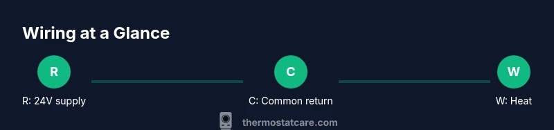
Thermostat wiring uses a small set of common color codes, but colors can vary by installer and equipment. In most 24-volt systems, red (R) is the supply, white (W) controls heat, yellow (Y) controls cooling, green (G) runs the fan, and blue or brown (C) serves as the common return. Orange (O) or blue (B) can be used for heat pump changeover, while other colors may appear in older systems. A practical rule is to verify each wire’s function at the furnace or air handler and then trace it to the thermostat base. Documenting your findings ensures you don’t mix up R with C or W. If you’re replacing a thermostat, confirm that the new model supports the existing wire configuration or requires a C-wire for power.
Safety Protocols Before You Start
Power down the system at both the thermostat and the HVAC panel whenever possible. Do not work on live low-voltage circuits. Use a non-contact voltage tester to confirm the absence of high voltage, and keep metal tools away from exposed conductors. When you remove the thermostat cover, label each wire and take a photo for reference. Work on a clean, dry surface and limit the number of wires that you handle at once to prevent cross-connecting. If you must test continuity, use the multimeter with the power off, and never test between live lines. By following these safety steps, you minimize shock risk and protect both the thermostat and furnace controls.
How to Inspect the Thermostat Cable and Terminals
Inspect the cable sheath for wear, damaged insulation, or pinched conductors. Check that each wire is securely fastened under its terminal screw and that there are no stray strands loose in the terminal block. If you discover corrosion or frayed wires, replace the affected section or the entire cable. Confirm that the thermostat’s screw terminals match the wires’ labels (R, C, W, Y, G, O/B). A clean, labeled junction at the thermostat base simplifies future maintenance and upgrades. When you reassemble, gently press the wires back in place to avoid pinching or bending them, and torque screws to the manufacturer’s specification.
Tip: Keep a simple wiring map as a reference card for future work.
Testing for a C-Wire and Common Alternatives
The C-wire is the return path for power in most smart and programmable thermostats. If your current cable lacks a dedicated C-wire, you have a few options: use a power-extender kit (for compatible models), repurpose an unused conductor (if present) by mapping it as C, or install a separate C-wire from the furnace control board. When testing, verify 24 VAC between R and C with the system powered and the thermostat connected. If you don’t see voltage, recheck the connections and confirm you are measuring across the correct terminals. Thermostat Care analysis notes that many thermostat issues originate from misidentified or loose C-wire connections, so double-checking this wire is a high-value step.
Step-by-Step Wiring Check for Common Thermostat Models
- Remove the thermostat faceplate and document all current connections. 2) Compare wire colors to terminal labels on the thermostat base and furnace control board. 3) Verify that each wire is firmly attached under its terminal screw and that no insulation is nicked. 4) Use a multimeter to verify continuity and 24 VAC between R and C when the system is energized. 5) If a required wire is missing (such as C), choose an approved method (new wire, extender kit, or adapter) and install per manufacturer guidelines. 6) Reattach the thermostat cover and run a test cycle to confirm proper operation. 7) Label wires for easy future reference and update your wiring diagram. 8) Store any spare conductors safely in the thermostat box.
Troubleshooting Common Wiring Issues
Loose terminals, frayed insulation, or mismatched wire-to-terminal connections frequently cause thermostat outages. If the thermostat reads “no power,” recheck the R and C connections first. A common mistake is mixing up W and Y on heat pump systems; this can cause the system to run cooling on a heating call. When wires are colored in nonstandard ways, test each connection with the HVAC powered down to prevent mis-wiring. If a professional fault exists in the furnace or air handler board, do not attempt to replace internal components yourself—call a qualified HVAC technician for service.
Upgrading or Replacing Wiring: When to Seek Help
If you discover damaged conductors, suspect a compromised furnace control board, or feel unsure about running new cable through walls, it’s wise to seek help. An experienced technician can verify compatibility, ensure electrical codes are met, and install a proper C-wire or alternative powering method. For homeowners comfortable with basic electrical work, upgrading wiring with caution and following the device manufacturer’s wiring diagram can be a satisfying DIY project. In all cases, keep safety at the forefront and document changes for future maintenance.
Authority and Further Reading
-
Wiring basics and safety guidelines from reputable sources help you stay compliant and safe. Always cross-check with official guidance when planning a wiring project. This article references general best practices and should not substitute for professional instruction.
-
Alternately, consult recognized technical resources for additional context and standards. The goal is to maintain a safe, reliable thermostat system and to understand how the thermostat wire interacts with your HVAC equipment.
Authority Sources
- https://www.energy.gov
- https://www.osha.gov
- https://www.nist.gov
Tools & Materials
- Non-contact voltage tester(Confirm absence of hazardous voltage at the thermostat base and furnace terminals)
- Digital multimeter (with AC voltage setting)(Test for 24 VAC between R and C when system is powered)
- Screwdrivers (Phillips and flat-head)(Remove thermostat faceplate and terminal screws)
- Wire stripper/caper pliers(Prepare wires for terminal insertion)
- Electrical tape(Label and secure wires)
- Small label tape or markers(Label each conductor for later reference)
- Replacement thermostat wires (if needed)(For extending or replacing a damaged cable)
- Wiring diagram or map(Document current connections for future maintenance)
Steps
Estimated time: 30-60 minutes
- 1
Power down and prep
Turn off the HVAC system at the furnace or air handler and switch off the thermostat. Remove the thermostat cover and label each wire. Take a reference photo for accuracy, then set tools within reach for quick access.
Tip: Label wires before disconnecting them to avoid misplacement. - 2
Identify wires and terminals
Match each conductor to its labeled terminal on the thermostat base (R, C, W, Y, G, O/B). If a color doesn’t match the standard function, trace the wire back to the furnace control board to confirm its role.
Tip: Use a color-to-function map for consistency. - 3
Test for 24 VAC power
With the system powered (if safe to do so), measure between R and C using the multimeter to confirm supply. If no voltage, recheck connections and ensure the thermostat is wired to the correct furnace terminals.
Tip: Only test live circuits with caution and proper PPE. - 4
Check for a C-wire availability
If there is no dedicated C-wire, determine if the spare conductor can be repurposed or if a power extender kit is appropriate for your model.
Tip: Avoid repurposing essential wires without verifying function. - 5
Plan for any replacements
If you need to run new cable, plan the route, check for building codes, and consider using the shortest, straightest path. Capture a wiring diagram before making changes.
Tip: Pre-visit your route with a stud finder and ceiling access checks. - 6
Reassemble and test
Reconnect wires to the correct terminals, replace the cover, and power the system back on. Run a test cycle to ensure heating, cooling, and fan operate as expected.
Tip: Test each function separately to identify miswiring quickly. - 7
Document changes
Update your wiring map and thermostat settings to reflect any changes. Keep notes for future maintenance or upgrades.
Tip: Keep a digital or physical copy accessible near the thermostat. - 8
Evaluate upgrade options
If your thermostat requires more power or you plan smart features, assess C-wire needs, compatibility, and potential sensor placements before purchasing.
Tip: Choose a model that supports your wiring configuration.
Questions & Answers
What is a C-wire and why is it important?
The C-wire provides a common return path for power to the thermostat, enabling smart features and reliable operation. Without a proper C-wire, some thermostats may not power correctly or stay on. Always verify C-wire availability when upgrading.
A C-wire is the common return for power to your thermostat, enabling features like Wi‑Fi. If you upgrade, make sure you have a real C-wire available.
Can I reuse existing wires if the C-wire is missing?
Yes, in some cases you can repurpose an unused spare conductor as C, or use a dedicated power extender kit designed for your thermostat. Check compatibility and follow the manufacturer’s instructions.
You might repurpose an unused wire or use a power extender kit, but always verify compatibility first.
Is it safe to work on electrical wires?
Low-voltage thermostat wiring is generally safe, but mistakes can cause equipment damage or injury. Always disconnect power, use appropriate tools, and follow safety guidelines.
Low-voltage wiring is usually safe, but treat it with care and power off before you begin.
How do I know if my thermostat requires a C-wire?
Check the thermostat’s installation manual or model specifications. If the thermostat requires power for display or connected sensors, a C-wire is commonly needed.
Most modern thermostats need a C-wire for continuous power; check your model’s manual.
Should I hire a pro for thermostat wiring?
If you’re unsure about wiring, encounter damaged cables, or suspect a furnace control issue, hire a licensed HVAC technician. A pro ensures safe, code-compliant work and reliable results.
If you’re unsure or see damaged wires, it’s best to hire a pro.
Watch Video
What to Remember
- Identify each thermostat wire before touching terminals
- Verify 24 VAC power and correct C-wire presence
- Label wires and document wiring map for future work
- Avoid dangerous wiring mistakes by following safety steps
- Know when to upgrade wiring or call a pro